Motor Fundamentals |
| |
Electric motors are designed to convert
electrical energy into mechanical energy to
perform some physical task or work. In
order to understand the types of motors
that are available as well as their performance
characteristics, some understanding
of the basic physical principles governing
motor design and operation are required.
Basic electric motor design encompasses
the laws of electricity and magnetism.
Motor feedback and control systems involve
semiconductor devices, microprocessors
and other elements of electronics.
And no discussion of motors would be
complete without a brief understanding of
the mechanical principles governing linear
and angular motion. |
|
Basic Electricity |
| Electric Current |
Atomic theory describes matter as an
aggregate of atoms. Each atom consists of
a nucleus containing positively charged
protons and electrically neutral particles
called neutrons. Revolving in orbits around
the positive nucleus are negatively charged
electrons.
In metallic conductors (such as copper),
one or more electrons from the outer orbits
become detached from each atom and
move randomly from one atom to another.
These are called free electrons. The positive
nucleus and the rest of the electrons
remain relatively fixed in position. Insulators,
on the other hand, contain virtually no
free electrons.
When an electric field is applied to a
conductor, free electrons will drift under
the influence of that electric field. Drifting
electrons will collide with stationary atoms causing additional free electrons to drift in
the same direction. This movement of electric
charge is called current.
The unit of measurement for current or
rate of charge flow is the ampere. We
speak of a direct current (DC) if the charges
always flow in the same direction, even
though the amount of charge flow per unit
time may vary. If the flow of charge reverses
its direction periodically, then we have
what is called alternating current (AC). A
more detailed description of direct and
alternating current is presentedhere. |
Conventional Current Flow:
Before the acceptance of the electron theory,
it was assumed that the direction of
current flow was from a positively charged
body to a negatively charged body. This
positive to negative flow of current is called
conventional current flow. However, in a
metallic conductor, it is electrons that carry
the charge from negative to positive. The
flow of current from negative to positive is
called electron flow. We will adopt conventional
current flow throughout this
Handbook. In the diagrams, the direction
of current will always be from positive to
negative. |
| |
| Potential Difference (V) |
Electrons will move between two points
of a conductor if there is a potential difference
(or a difference of “electric pressure”)
between the two points. Voltage is the
measure of the amount of pressure needed
to push electrons through a conductor. It is
analogous to a water pump that maintains a
pressure difference between its inlet and
outlet and results in water flow. Potential
difference and voltage are often used interchangeably.
The unit of potential difference or voltage
is the volt. A potential difference of
one volt will be dropped across two points
if a constant current of one ampere flowing between the two points results in a power
dissipation of one watt. |
| |
| Resistance (R) |
Resistance is defined as the opposition
to current flow. Although electrons may
flow in any substance, different materials
offer different resistance to their flow.
Those which make the transfer of electrons
relatively easy are called conductors
(copper, aluminum, steel, etc.), and those
which tend to impose substantial resistance
are called insulators (wood, paper, mica,
glass, etc.). Materials with a level of conductivity
between these two extremes are
called semiconductors (germanium, silicon).
These “in between” materials have
become increasingly useful in the application
of electrical energy.
The unit of electrical resistance is the
ohm (Ω). One ohm is defined as the resistance
of a conductor which will allow a
current flow of one ampere when a potential
difference of one volt is applied. The
resistance of a material is normally dependent
on temperature. In general, the resistance
of metallic conductors increases with
temperature. |
Ohm's Law:
Ohm’s law explains
the relationship between voltage, current
and resistance. It states that the amount of
current through a conductor is directly proportional
to voltage applied and inversely
proportional to the resistance of the conductor
or circuit:
I=V/R
A conductor obeys Ohm’s law when,
for a given temperature, the current it conducts
varies linearly with the applied voltage. |
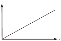 |
Current varies linearly with
applied
voltage in accordance with
Ohm’s law. |
|
Power:
Electricity is used to perform
some type of work or to generate heat.
Power is the rate at which work is done or
the rate at which heat is generated. The unit for power is the watt. The amount of
power dissipated is directly proportional to
the amount of current flow and voltage
applied:
P=VI |
Power Loss:
Power can also be
expressed as a function of resistance and
current. From Ohm’s law we learned that
V = IR. So if you substitute IR for V in the
power formula you have:
P=(IR)I or P=I2R
The windings in an electric motor consist
of many turns of copper wires. Although
copper is an excellent conductor,
the substantial total length of wire required
in the windings results in measurable power
loss because the resistance of a wire increases
with its length. This I2R loss in the
motor is sometimes referred to as the copper
loss. |
Horsepower:
Electric motors are
rated in horsepower. One horsepower
equals approximately 746 watts. Horsepower
and watts are simply two different
ways to express power. |
Series Circuits:
The figure below
shows a simple series circuit with a voltage
source and resistors R1 and R2. A series
circuit is one that allows only one path for current flow. There are three rules which
govern series circuits.
- The total circuit resistance is the sum of
the individual resistance's in the circuit:
RT = R1 + R2 + ... + RN
- Current has the same value at any point
within a series circuit.
- The sum of the individual voltages
across resistors in a series circuit equals
the applied voltage:
V = V1 + V2
|
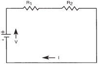 |
Simplified series circuit. |
|
Parallel Circuits: |
A simple parallel
circuit is one that allows two or more
paths for current flow. The resistors shown below are said to be connected in parallel.
There are also three rules which govern
parallel circuits.
- The voltage drop across each branch
of a parallel circuit is the same as the
applied voltage:
V = V1 = V2
- The total current in a parallel circuit is
equal to the sum of the branch currents:
I = I1 + I2
where I1 and I2 are currents flowing part
of through R1 and R2 respectively.
- The total resistance in a parallel circuit
is always less than or approximately
equal to the value of the smallest
resistance in any branch of the circuit.
Since I = I1 + I2 you can substitute V/R in place of I and arrive at: V/RT = V1/R1 + V2/R2
Since V = V1 = V2, you can substitute V(1/R1 + 1/R2) in the second part of
R1 R2
the above equation leaving you with:
V/RT = V(1/R1 + 1/R2) or 1/RT = 1/R1 + 1/R2
Therefore, the reciprocal of the total
resistance is the sum of the reciprocal of
the individual resistance's. Solving for R
results in:
R = 1/(1/R1 + 1/R2)
In general, for N resistors in parallel,
the equivalent resistance (R) is computed
as follows:
1/R = 1/R1 + 1/R2 + 1/R3 + 1/RN
|
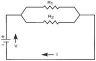 |
Simplified parallel circuit. |
|
| |
| Capacitance |
A capacitor is a device that stores electric
charge. Almost any insulated body can
hold a limited electric charge, and the
greater the surface area, the greater the
charge that can be stored. In practical use,
however, a capacitor is a compact system of conductors and insulators (dielectric) so
arranged that a large amount of electric
charge can be stored in a relatively small
volume.
The capacitance (C) is the measure of a
capacitor’s ability to store a charge on its
plates at a given voltage (V):
C = Q/V
Q, measured in coulombs, is the charge
stored in the capacitor. One coulomb has
an equivalent charge of about 6.24 x 10¹⁸
electrons.
The unit of capacitance (C) is the farad
(F). One farad is the capacitance of a capacitor
in which a charge of one coulomb
produces a change of one volt in potential
difference between its plates.
One farad is an extremely large unit of
capacitance. Based on the large physical
size needed to produce such a component,
smaller units of more convenient size such
as the microfarad (μF = 10-6F), and
picofarad (pF = 10-12F) are used in most
applications.
A simple capacitor can be made by
placing two identical metal plates in parallel
with an air gap between them. See figure below. It is known that the capacitance of a
parallel plate capacitor increases proportionally
with the area (A) of the plate and
decreases proportionally with the distance
(d) between them. We may thus write, C =
kA / d, where k is a constant.
|
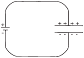 |
Parallel plate capacitor. |
|
It is also known that if a dielectric such
as glass is placed between the plates (see figure below), the capacitance is increased five to
ten times. In varying degrees, putting materials
like mylar, mica, wax or mineral oil
between the plates will all result in higher
capacitance. Different insulating materials
(dielectrics) offer different increases in capacitance.
The ratio of the capacitance
with the dielectric to that without the dielectric
is called the dielectric constant (k)
of the material. A vacuum has a dielectric
constant: k=1.
Dielectrics used in commercial capacitors
include air, oil, paper, wax, shellac,
mica, glass, bakelite, polyester and
polypropylene film. Most capacitors are
fabricated with strips of metal foil, as
plates, separated by dielectric strips of the
materials mentioned above. The foil and
dielectric strips are sandwiched, rolled and
encased into a compact form which is then
fitted with terminals. |
 |
Increased capacitance with
dielectric. |
|
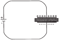
RC Circuit: |
The circuit shown above consists only of a battery and a
capacitor. Theoretically, with no resistance
in the circuit, the capacitor would charge
instantly. In reality however, when an electric
potential is applied across an uncharged
capacitor, the capacitor will not be
charged instantaneously, but at a rate that is
determined by both the capacitance and
the resistance of the circuit.
Similarly, when a capacitor discharges it
will not take place instantly. Rather, the
discharge current will diminish exponentially
over time.
The figure below illustrates a basic RC circuit.
The capacitor will be charged if the switch
is closed at the “a” position. If the switch is
then closed at the “b” position, the capacitor
will discharge. |
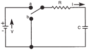 |
Basic RC Circuit |
|
With the resistor present in the circuit,
current will not flow as freely. More time
will be required to charge the capacitor.
Likewise, it will take longer for the
capacitor to discharge with the resistor in
the circuit.
With a resistor in the circuit, the voltage
across the capacitor rises more slowly. The
current flow acts directly opposite. When
the switch is first thrown to the “a” position
there is more current flow. As the voltage
across the capacitor reaches the battery
potential, current flow decreases. When
the capacitor voltage equals the battery
voltage level, current flow stops.
Q is the amount of charge on the capacitor
and is zero at time t = 0 (see figure below). Q
will increase as the current flows until it
reaches a maximum value (Q = CV), at
which point the current is zero. |
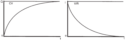 |
Curves for Q and I during charging |
|
In DC circuits, capacitors oppose
changes in voltage. The time delay for the
capacitor’s voltage to reach the supply
voltage is very useful because it can be
controlled. It depends on two factors:
- the resistance in the circuit, and
- the size of the capacitor.
|
Time Constant: |
The time it takes
a capacitor to charge to 63% of the supply
voltage is called the capacitive time constant
(T). It can be calculated using the
formula:
T = RC
A capacitor discharges in a similar manner
as shown below. The current is
now negative, because it flows in the opposite
direction during discharging.
A capacitor is said to be fully charged
or fully discharged after five RC time constants.
The figures illustrate that current
varies exponentially with time during the
charging and discharging of an RC circuit
when a DC source is applied. |
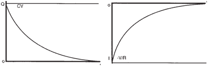 |
Curves for Q and I during discharging |
|
| |
| |