Motor Fundamentals |
| |
| GENERATORS
AND BASIC
AC CIRCUITS |
| Electric motors are generally divided
into DC and AC (induction) types. Each
has its own operating characteristics and
advantages. In this section, a brief review
of direct current vs. alternating current will
be presented followed by discussions of
various AC circuits. |
Direct Current: |
Direct current can
be obtained through the chemical reactions
in primary cells or secondary cells. Primary
cells are batteries that consume their active
materials when releasing electric energy
and hence, are not reusable. Secondary
cells (or storage cells), on the other hand,
can be recharged by applying electricity in
the reverse direction, thus reversing the
chemical reaction.
Direct current is commonly produced
by DC generators in which mechanical
energy supplied by steam turbines, water
wheels, water turbines or internal combustion
engines is converted into electric energy.
A brief description of a simple DC generator
will be presented later.
In addition to the above, direct current
can be generated from thermal energy (i.e.,
thermocouple) and light energy (solar
cells). Furthermore, alternating current can
be converted into direct current through the
use of rectifiers. |
Alternating Current: |
The most
commonly supplied form of electric energy
is alternating current. The main reason for
the widespread use of AC is the fact that
the voltage can be readily stepped up or
down through the use of transformers.
Voltage is stepped up for long distance
transmissions and stepped down for sub distribution.
The voltage is stepped down
even further for industrial and home use. For a given power (VI), stepping up the
voltage decreases the current and consequently
reduces the (I2R) power loss in the
power lines.
There are many additional advantages
to AC. For example, AC is used to run
induction motors (which do not require a
direct supply of current to the rotating
member and consequently avoid the
problems associated with brush and
commutator wear in DC motors).
However, there are cases (battery
charging, electroplating, etc.) where DC
must be used. Motor applications in which
adjustable speed control is important are
generally operated from a DC source.
However, in most of these cases, the
energy is originally generated as AC and
then rectified and converted to DC.
Alternating current can be supplied by
generators (which will be discussed next)
and by devices called inverters which convert
DC into AC. |
| |
| AC and DC Generators |
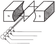
The figure below shows a simple AC generator.
In simple terms, a magnetic field or
flux is established between the poles of a
magnet. When a coil of conductive material
is introduced into the air gap perpendicular
to the flux and rotated mechanically at a
uniform speed, it will cut the flux and induce
an emf that causes a current to flow in
the closed circuit formed by the slip rings (X and Y), the brushes and the load
resistor (R). With a full 360 degree revolution
of the coil, the current flows first in one
direction and then in the other, producing
an alternating current.
If the coil in the figure below were rotated
counterclockwise at a constant speed, the
top of the coil (cd) would cut the flux in a
downward direction, while the bottom (ab)
would cut the flux in an upward direction.
By the right-hand rule of induction, the
resulting current produced in the coil by
reaction with the flux would flow from a to
b and from c to d during the first 180
degrees of rotation. |
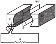 |
Simple alternating current AC
generator. |
|
| As the coil continued around to its original
position, ab would cut the flux downward
and cd upward, causing an opposite
current flow from d to c and b to a. One
360 degree rotation of the coil is equivalent
to one cycle. Since standard available current
is 60 Hz (cycles per second), the coil
would be rotated sixty full rotations per
second to deliver standard 60 Hz AC. This
back and forth flow of current can be represented
graphically as a sine wave in the figure below. |
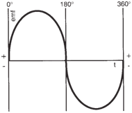 |
Sine wave characteristic of AC
current during one cycle (360°). |
|
Without going into the mathematical
details, the wave shape of the induced emf
can be explained by the fact that the rate of
change of flux (Ω) through the surface a-bc-
d formed by the wire loop is a sinusoidal function of time. Since by Faraday’s law the induced emf is proportional
to the rate of change of flux, a
sinusoidal induced emf results.
For DC generators, the same principle
of flux cutting holds true, except that instead
of the slip rings, a synchronous mechanical
switching device called a commutator
is used. See figure below. |
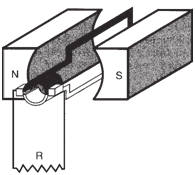 |
Simple DC generator. |
|
The arrangement of commutator and
brushes allows the connections to the external
circuit (in our case, the resistor, R) to
be interchanged at the instant when the emf
in the coil reverses, thus maintaining a unidirectional
(although pulsating) current (see
figure below). |
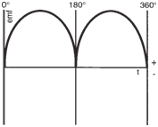 |
Induced emf from the simple
DC generator. |
|
The pulsating emf from the simple DC
generator is not very useful when relatively
uniform DC voltage is required. In practice,
a DC generator has a large number of
coils and a commutator with many segments. Each coil is connected to its own
pair of commutator segments. The brushes
make contact with each coil for a short
period of time when the emf in that coil is
near its maximum value. The figure below illustrates
the emf output of a DC generator
with four evenly spaced coils connected to
an eight-segment commutator. The dotted
curves are the induced emfs (eight emfs for
every revolution). The solid line is the output
voltage of the generator. |
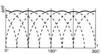 |
Output of DC generator with
four coils and an eight-segment commutator. |
|
Two-Phase and Three-
Phase AC: |
| In addition to single-phase
AC produced by the generator described
above, alternating current may be supplied
as both two and three-phase. Using the
example of the simple single coil AC generator
described before, if we were to add
a second coil with its loop arranged perpendicular
to the original (see figure below)
and rotate them mechanically with a uniform speed, two-phase voltage would be
produced. |
 |
Simple two-phase AC
generator. |
|
| The resulting two-phase voltage sequence
is shown below, where one
phase lags the other phase by 90 degrees. |
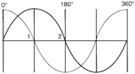 |
Wave shapes produced by
two-phase AC. |
|
If we were to add one more coil and
space the three at 120 degrees to each
other, the same generator
would now produce three-phase current
(see figure below). |
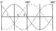 |
Wave shapes produced by
three-phase AC. |
|
| Two and three-phase current are used
in both poly phase and induction motor
design. Since both will produce a rotating produce a rotating magnetic field in the
stator bore, the rotor will follow the field
and result in rotation. |
The Delta (Δ)-Connection
and Wye-Connection: |
Although it
is shown above that each coil of the
three-phase AC generator is provided with
its own pair of slip rings and brushes, the
practical design of a three-phase generator
has only three slip rings and brushes. This
is accomplished by either the Delta-connection
or Wye-connection of the three
coils (1, 2, and 3) in the generator.
The figure below shows a Delta-connection
with output terminals (a, b and c). The
three pairs of terminals (a-b, b-c, and c-a)
provide a three-phase output like the one
shown in Fig. 1-31. The line voltage (voltage
from any pair of the terminals) is the
same as the coil voltage (voltage across
each coil). The line current, however, is 3
times the coil current.
The Wye-connection shown below again has terminals a, b, and c. There is
also a common point called the neutral in
the middle (O). Again, the terminal pairs
(a-b, b-c, and c-a) provide a three-phase
supply. In this connection, the line voltage
is 3 times the coil voltage while the line
current is the same as the coil current. The
neutral point may be grounded. It can be
brought out to the power user via a four-wire power system for a dual voltage
supply.
For example, in a 120/208-volt system,
a power user can obtain 208 volt, threephase
output by using the three wires from
a, b, and c. Furthermore, single-phase,
120 volt power can be tapped from either
O-a, O-b or O-c. |
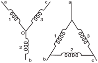 |
Delta-connection of three coils
(right), Wye-connection of three coils
(left). |
|
| |
| AC Circuits |
While many forms of “alternating current”
are non sinusoidal, the popular use of
the term alternating current, or AC, usually
implies sinusoidal voltage or current. Electro-
magnetic devices such as motors consist
of ferromagnetic materials with nonlinear
voltage/current relationships. Thus,
current will not be pure sinusoidal. |
Root-Mean-Square or Effective
Values, and Power Factor
in AC Circuits: |
| The voltage (V) and
current (I) in a sinusoidal alternating current
circuit consisting of linear devices are generally
written as: |
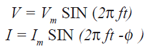 |
Here, Vm and Im are the peak values of
V and I respectively, f is the frequency in
hertz (Hz) and φ is the phase angle (in radians)
between the current and the applied
voltage. (See figure below). Since the positive
portion of the voltage or current is the mirror
image of the negative portion, the average value in one complete cycle is
zero. |
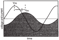 |
Vm and Im are out of phase by
an angle φ. |
|
This result provides no useful information
about the magnitude. One useful way
of specifying the magnitude of the AC is to
compute its root-mean-square (rms) value
which is alternatively called the effective
value.
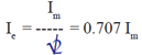
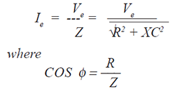
The effective value of alternating current
is that which will produce the same amount
of heat or power in a resistance as the corresponding
value of direct current. The
effective value of current (I) is obtained by
first computing the average of the square of
the current and then taking the square root
of the result. Without performing the computation,
we will just state that the effective
value of current Ie is: |
 |
| Similarly, the effective voltage (Ve) is: |
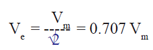 |
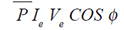
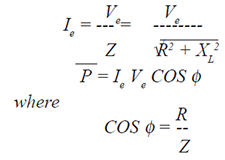
| Then the average power (P) of the circuit
can be shown to be: |
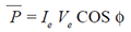 |
| The quantity (COS φ) is called the
power factor of the circuit. If the current (I)
and voltage (V) are in phase (i.e., f = 0)
then we have the maximum power (P = Ie
Ve). Stated another way, only the component
of Ie in phase with Ve contributes to
the average power. The other component
may be said to be “watt less.” |
| |
| Pure Resistance
AC Circuit |
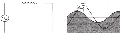
A pure resistance circuit is one in which
there is no significant inductive or capacitive
component. In such a circuit, the current
and voltage would both be sinusoidal
and in phase ( φ = 0). See figure below. |
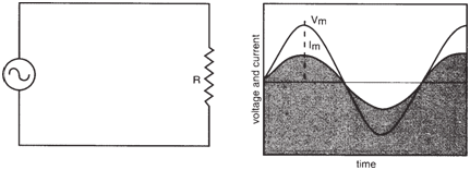 |
Pure resistance (R) circuit. Vm and Im are in phase, φ = 0. |
|
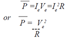
| Pure
resistance circuits can be treated as if they were DC circuits if the effective values of
current and voltage (Ie and Ve) are used: |
 |
| Since the average power: |
 |
| then for the phase angle f = 0°: |
 |
| |
| Pure Inductance
AC Circuit |
| In an inductive circuit, the counter emf
(or self-inductance) of the inductor will
offer opposition to any change in the
current. Since an alternating current is one
that is continually changing, there will be a
continual opposition to the flow of current
corresponding in value to the rate of
change of current. |
Inductive Reactance: |
| The opposition
to the current flow in an inductance
circuit is called the inductive reactance
(XL), which is given by the formula: |
 |
where XL is in ohms, f is the frequency in
Hz and L is the inductance in Henrys.
The phase angle (φ) is +90°. Thus, a
pure inductance circuit will not only offer
opposition to current flow but will also
cause the current to lag behind the voltage
by 90° (figure below). |
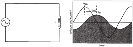 |
Pure inductance (L) circuit. I lags V, φ = 90°. |
|
| The effective current (Ie) and average
power (P) are: |
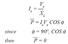 |
| Therefore, there is no power loss in a
pure inductance circuit. |
| |
| Pure Capacitance
AC Circuit |
A capacitor placed in a circuit also presents
opposition to current flow. This is
due to the limitation that charge will flow
into the capacitor and accumulate only to
the level proportional to the applied voltage.
No further charge will flow in or out
until there is a corresponding change in
applied voltage.
Thus, the current in a capacitor
circuit is proportional to the slope of the
voltage curve. The slope is highest for a
sinusoid when V = 0 and the current flow
is at its maximum. The slope is zero when
V is at its peak (positive or negative) and
this corresponds to a zero current flow. |
Capacitive Reactance: |
| The
opposition to current flow in a capacitance circuit is called the cap active reactance
(Xc). Its value is given by the formula: |
 |
where Xc is in ohms, f is the frequency in
Hz and C is the capacitance in Farads.
The phase angle (f ) in this circuit is -
90°. Thus, in a pure capacitance circuit,
the current leads the voltage by 90°. |
| The effective current (Ie ) is: |
 |
| Since φ = -90°, COS φ = 0. There is
also no power loss in a pure capacitance
circuit. |
| |
| RL AC Circuit |
When R and L are connected in series
in an AC circuit, we have the series RL
circuit shown below. Both the resistance
(R) are the inductive reactance (XL) of the inductor offer opposition to current
flow. |
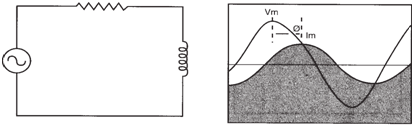 |
Series RL circuit. I lags V. 0 < φ < 90°. |
|
Impedance in RL Circuit: |
| The
combined effect of R and XL is called the
impedance (Z) which is expressed in ohms: |
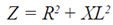 |
The impedance can be represented as
the hypotenuse of a right angle triangle
whose sides are R and XL (see figure below).
This is also referred to as the impedance
diagram.
The phase angle (φ) in this circuit happens
to be the angle between Z and R (or,
cos φ = R/Z). Since is between 0° and
90°, the current (I) in the circuit lags behind
the voltage by an angle between 0° to 90°
depending on the values of R and XL. |
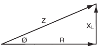 |
Impedance diagram of an RL
circuit. |
|
| The effective current (Ie) and average
power (P) are: |
 |
| Since no power is lost in the inductance,
then: |
 |
| |
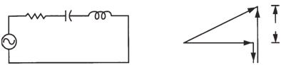
| RC AC Circuit |
Similar to the RL circuit described previously,
resistance (R) and capacitive reactance
(Xc) will both oppose current flow in
an AC circuit. Unlike the RL circuit, increasing
C or the frequency results in a
decrease in Xc and an increase in current.
See figure below. |
 |
RC circuit. I leads V. -90° < φ< 0. |
|
Impedance in RC Circuit: |
| The impedance (Z) in this case is: |
 |
| The vectorial representation is shown below, where XC is pointing downwards
and represents a “negative” Vector. |
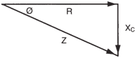 |
Impedance diagram of an RC
circuit. |
|
| The phase angle (φ) is now between -
90° and 0°, and: |
 |
The current (I) in the circuit lags the
voltage by an angle (φ) between 0° and
90° depending on the values of R and XC.
The effective current (Ie) is: |
 |
| Since no power is lost in the capacitance: |
 |
| |
| RLC AC Circuit |
| To further generalize the AC series circuit,
we should consider the RLC circuit
shown below. |
 |
Basic RLC circuit (left) and vector diagram (right). |
|
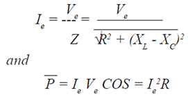
| The impedance of this
circuit is: |
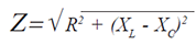 |
The vector diagram of the above relationship
is also shown in the figure above. The
phase angle ( φ ) in an RLC circuit is between
-90° and +90° where: |
 |
| If XL > XC, then the current in the circuit
will be lagging the voltage. If XL < XC,
then the current will be leading the voltage.
If XL = XC, the circuit is said to be resonant
and will behave as purely resistive.
The effective current (Ie) is: |
 |
| |