Motor Fundamentals |
| |
| Basic Magnetism |
Electric motors derive their characteristic
ability to convert electrical energy to
mechanical energy from magneto static
force. Magneto static forces result from
electric charges in motion. These charges may flow freely through space, in a conductor,
or exist as spinning electrons of the
atoms that make up magnetic materials.
As early as 640 B.C. certain natural
magnets were known to exist. Nearly 2000
years later, two simple laws governing their
behavior were discovered:
- Like poles repel each other, while unlike
poles attract.
- The force of attraction or repulsion is
proportional to the inverse square of the
distance between the poles.
|
| Magnetic Field |
| An important property of magnets is
that they can exert forces on one another
without being in actual contact. This is explained
by the existence of a magnetic field
around a magnetized body. The magnetic
field of the bar magnet (see figure below) is represented
by the lines radiating out from the
north pole and entering the south pole. Any
other magnet placed in this magnetic field
will experience a force. Forces will also be exerted on electrons moving through a
magnetic field. |
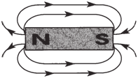 |
Flux field pattern of a simple
bar magnet. |
|
Flux Density: |
| The magnetic field
lines in Fig. 1-9 are collectively referred to
as the magnetic flux. Magnetic flux density
is the amount of magnetic flux passing
through a unit area plane at a right angle to
the magnetic field. It is a measure of how
concentrated the magnetic field is in a given
area. Magnetic flux density (B) is a vector
quantity. That is, it has magnitude as well
as direction. |
| |
| Magnetism at the
Atomic Level |
While ferrous materials, like iron, are
strongly magnetic, many materials show at
least some magnetic properties. Paramagnetic
materials, mostly metals, exhibit very
weak attraction to a magnet. The rest of
the metals and nonmetals are diamagnetic
—very weakly repelled by a magnet. Only
the ferrous materials, some specialized
alloys, and ceramics have sufficiently strong
magnetic properties to be of commercial
use.
No more than two electrons can share
the same electron level or shell of an isolated
atom. Diamagnetic materials have two
electrons in each shell, spinning in opposite
directions. See figure below (a).. Since the magnetic
response of a material is dependent
upon the net magnetic moment of the atoms,
this balanced symmetrical motion
produces a magnetic “moment” of near zero. Quite simply, the fields produced by
the counter spinning electrons cancel each
other.
For the paramagnetic elements in which
the electron shells are naturally asymmetric
(see figure below), each atom has a weak but
significant magnetic field. However, few of
the paramagnetic elements are magnetically
very strong. These are called the ferromagnetic
elements.
Ferromagnetism is the result of the
asymmetrical arrangement of electrons in
atoms in combination with a coupling or
aligning of one atom’s magnetic field with
that of an adjacent atom. This results in a
strong magnetic response. This “exchange
coupling” occurs only in materials in which
the spacing between atoms falls within a
certain range.
In iron, cobalt, nickel and gadolinium,
the net magnetic moment is strong enough,
and the atoms close enough, for spontaneous
magnetic alignment of adjacent atoms
to occur. Solid ferromagnetic materials
conduct magnetic flux in the alignment
direction.
|
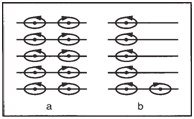 |
Arrangement of: a) electrons
in diamagnetic materials (left), and
b) electrons in magnetic materials (right). |
|
| |
| Electric Current and
Magnetic Fields |
In 1820, Oersted discovered that an
electric current passing through a conductor
would establish a magnetic field. This discovery
of the relationship between electricity
and magnetism led to the development of most of our modern electric machines.
The magnetic field around a current carrying
straight conductor takes the form
of concentric cylinders perpendicular to the
conductor. In the figure below, the current is
shown emerging from the page and the flux
lines, shown as concentric circles, are
flowing counterclockwise. When the direction
of the current is reversed, the flux lines
flow clockwise. |
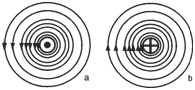 |
Direction of flux flow with
a) current flowing out of page (left), and
b) flux flow with current flowing into page
(right). |
|
| The right-hand rule, shown below,
can be used to determine either the direction
of the magnetic field or the direction of
current when the other one is known. |
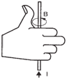 |
Right-hand rule: thumb points
in direction of current, palm curls in direction
of magnetic field. |
|
| When the current-carrying conductor is
formed into a loop as shown below,
the faces of the loop will show magnetic
polarities. That is, all of the magnetic field
lines enter the loop at one face and leave at
the other, thus acting as a disc magnet. |
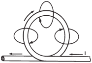 |
Direction of magnetic flux
when an energized conductor is formed
into a loop. |
|
| The
polarities will be more pronounced and the
magnetic field will be much stronger if we
wind a number of loops into a solenoid
(shown below). |
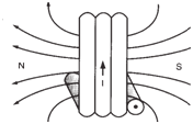 |
Flux characteristics in simple
soleniod. |
|
The magnetic field developed by the
solenoid resembles that of a bar magnet.
The flux lines form continuous loops, leaving
the solenoid at one end and returning at
the other, thus establishing north and south
poles.
The magnetic flux (Φ) of a given solenoid
is directly proportional to the current
(I) it carries. The same holds true for a
straight conductor or a single loop of wire.
For solenoids with different numbers of
turns and currents, the magnetic flux is proportional
to the product of the number of
turns and the amount of current. |
Properties of Magnetic
Materials: |
| When a ferromagnetic material,
like an iron bar, is placed in a magnetic
field, it presents a low resistance path to
the flow of flux. This results in a “crowding
effect,” as flux seeks to flow through it and
flux density increases in the gaps at the
ends of the bar. See figure below. Iron, cobalt,
nickel, some rare earth metals and a variety of other ferromagnetic alloys and
compounds are excellent magnetic conductors
with high permeability. |
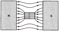 |
Effect of an iron bar on a
magnetic field. |
|
Permeability and Magnetic
Field Strength:
|
| Permeability (μ) is a
measure of how well a material will conduct
magnetic flux. It is related to magnetic
flux density (B) and magnetic field strength
(H) in the following equations: |
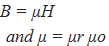 |
where μo = 4π x 10-7 (in SI units) and μr is
the relative permeability with a value of
unity (1) in free space.
The magnetic field strength (H) is
measured in amperes per meter. The
following formula shows that for a solenoid
(conductor loop) with length (1) and a
number of turns (N), the magnetic field
strength within the solenoid is proportional
to the current (I): |
 |
| For a given solenoid and current, H
remains the same regardless of any material
placed inside the solenoid. However, the
magnetic flux density (B) will be directly
proportional to the permeability (μ) of the
material. |
Magnetization, Demagnetization
and Hysteresis: |
If a piece
of iron is used as the core of a solenoid
and the current is increased slowly (increasing
the magnetic field strength, H), the iron will be magnetized and follow the
magnetization curve (abcd) as shown below.
The magnetization curve shows how the
flux density (B) varies with the field
strength (H). And since B = μH, it also
shows how the permeability (μ) varies with
the field strength. When H is gradually increased,
the flux density (B) increases
slowly at first (section ab of the curve).
Then, as H is further increased, the curve
rises steeply (bc of the curve). Finally,
magnetic saturation is approached (near d)
where the curve flattens out.
If the current is then gradually decreased,
flux density (B) will decrease but
the demagnetization curve will not retrace
the path (dcba). Instead, it will follow a
path de, where at point e, even though the
current has been reduced to zero, there is
some residual magnetism. If we then gradually
increase the current in the reverse
direction, creating -H, the iron will be completely
demagnetized at point f. By further
increasing the current and then slowly decreasing
it, we will go through points g, h, i
and d. The complete loop (defghi) is called
a hysteresis loop and represents a virtual
“fingerprint” for the material being used.
See figure below. |
 |
Magnetization curve and
hysteresis loop. |
|
| As iron is magnetized and demagnetized,
work must be done to align and realign
its atoms, and this work takes the form of heat. In alternating current machines
(i.e., motors and generators), the
magnetizing and demagnetizing process
takes place many times a second and hysteresis
loss (heat) may be considerable,
resulting in lower operating efficiency. The
hysteresis loss for one cycle of alternating
current is equal to the area enclosed by the
hysteresis loop. |
Motor Action: |
If we place a current-
carrying conductor (see figure below - a) between
opposite magnetic poles (see figure below - b), the flux lines below the conductor
will move from left to right, while those
above the conductor will travel in the opposite
direction (see figure
below - c). The result is
a strong magnetic field below the conductor
and a weak field above, and the conductor
will be pushed in an upward direction.
This is the basic principle of electric
motors and is sometimes called “motor
action.” |
 |
a) Flux pattern around an energized conductor (left), b) flux between two
magnetic poles (center), and c) effect of placing an energized conductor in a uniform
magnetic field (right). |
|
| The force (F) on the conductor is a
product of the magnetic flux density (B),
the conductor’s current(I) and the length of the conductor(I): |
 |
where we have assumed that the conductor
is at a right angle to the magnetic flux
density (B).
An easy way to remember the direction
of motion is to apply the right-hand rule,
shown below. |
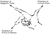 |
Right-hand rule for force on a
conductor in a magnetic field. |
|
| |
| Induced EMF |
| In general, if a conductor cuts across
the flux lines of a magnetic field or vice
versa, an emf is induced in the conductor.
If the direction of the flux lines and the conductor
are parallel, there is no induced emf. |
Generator Action: |
| If the conductor
in the figure below is moved vertically up
or down in the magnetic field, an electromotive
force is generated in the conductor.
If the conductor is connected to a closed
circuit, current will flow. This is the basic
principle of electric generators and is also
called “generator action.” |
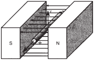 |
Direction of induced emf in a
conductor-cutting flux. |
|
| The induced emf is a product of the
velocity of the motion (v), the magnetic
flux density (B), and the length of the
conductor (l): |
 |
The relationship is valid only if the motion
of the conductor is perpendicular to
the flux lines.
The direction of induced emf depends
on the direction of motion of the conductor
and the direction of the magnetic field. This relationship can be shown by Fleming’s
left-hand rule for electromagnetism. |
Faraday’s Law: |
We have seen
that any conductor cutting across a magnetic
field will produce an emf. However,
this is only a special case of the more general
law of induction established by Faraday
in 1831: “If the total flux linking a circuit
changes with time, there will be an
induced emf in the circuit.”
If we were to wind two coils around a
steel bar, as in the figure below, connecting one
to a battery with a simple on/off switch and
the other to a sensitive galvanometer, the
effect of closing the switch would produce
a change in current and a change in the
field thereby inducing a current in Coil 2.
Similarly, if we were to open the circuit, a
current would again register in Coil 2. |
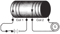 |
Magnetically coupled coils
wound around a steel bar. |
|
| The induced emf in Coil 2 is mathematically
related to the change of flux as
follows: |
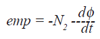 |
Where N2 is the number of turns in Coil 2
and dφ/dt is the rate of change of flux, the
minus sign indicates that the induced current
in Coil 2 will flow in such a way as to
oppose the change of flux due to the
change of current in Coil 1.
Since both coils are wound in the same
direction, the induced current will flow in
the direction shown in the figure above when the
switch is closed. This induced current in
Coil2 sets up a magnetic field opposes the sudden increase of flux created by
current flowing in Coil 1. If the switch is
then opened, the current in Coil 2 will flow
in the opposite direction creating a flux that
opposes the sudden decline of flux from
Coil 1. |
| |
| Inductance (L) |
The change of magnetic flux due to
switching in the figure above would also produce
a counter emf (cemf) in Coil 1 itself. The
cemf opposes the build-up or decline of
current in the same circuit. The ability of a
coil to store energy and oppose the buildup
of current is called inductance.
For a given coil, the change of magnetic
flux is proportional to the change of current.
Thus, the cemf may be expressed as
follows: |
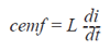 |
| where L is called the inductance of the coil.
A coil or circuit is said to have an inductance
of one Henry when a current changing
at the rate of one ampere/second induces
one volt in it. |
RL Circuit: |
| In the section Basic Electricity we
learned that there is a delay in the rise or
fall of the current in an RC circuit. The RL
circuit, shown below, has a similar
property. |
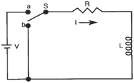 |
Basic RL circuit. |
|
| When the switch (S) is closed at a, the
current in the resistor starts to rise. However,
the cemf presented by the inductor
(L) opposes the rise of the current, thus the
resistor responds to the difference between the battery voltage(V) and the cemf of hte
indicator. As a result, the current rises exponentially
as shown figure below. |
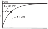 |
Current rise in RL circuit. |
|
If we allow enough time for the current
to reach V/R and then close the switch at
b, current will continue to flow but diminish
as the stored magnetic field energy is dissipated
through the resistor. |
RL Time Constant: |
The time
constant is the time at which te current in
the circuit will rise to 63% of its final value
(V/R) or decay to 37% of its initial value. It
is represented by the formula: |
 |
| The time constant can be controlled by
varying the resistance or inductance of the
circuit. Decreasing the circuit resistance
increases the time constant. Increasing the
inductance will also increase the time constant.
Thus, the larger the time constant, the
longer it takes the current to reach its final
value. The current in an RL circuit will rise
or fall to its final value after five time constants
(within 99.3%). |
| |