Special Motors |
| |
Most applications, if studied carefully,
will have parameters that will be satisfied
more effectively by one type of motor.
There are other criteria such as continuous
operation at very slow speeds, short duty
cycles or high torque requirements within a
limited mounting space, to name just a few,
that can place very unusual demands on
fractional horsepower motors.
To meet these unique design criteria,
motor manufacturers have developed a
variety of special purpose motors that
exceed the specifications of many common
motor designs. In this Chapter we will take
a brief look at some of these special
purpose motors. |
| |
| FRACTIONAL
HORSEPOWER
GEARMOTORS |
For low speed drive applications,
electric motor manufacturers have
developed compact and efficient integral
gearheads. When coupled with common
fractional horsepower (fhp) electric
motors, these gearheads provide speedreducing/
torque-multiplying units of
exceptional reliability. In any application
which requires shaft speeds slower than
that of a “straight” motor, fhp gearmotors
can be a highly desirable alternative to
conventional belts, gears and chains.
Gearmotors free the original equipment
manufacturer of the burden of designing
external reduction devices. They also offer
original equipment designers a highlyengineered,
field-tested, single-source
drive system.
Because gearmotors are rated and selected
based on both the motor specifications and
the gearhead specifications, they present a
unique situation. |
| |
| LOW SPEED AC
SYNCHRONOUS
MOTORS |
Some applications require high torque
combined with rapid stop and start characteristics.
Low speed AC synchronous motors
are appropriate for applications which
require six or more starts per minute. Since
the motor has no significant current rise on
starting, there is no additional heat rise with
repeated starts.
Unlike gearmotors, there is no backlash
associated with low speed synchronous
motors. As a result, they are used in place
of gearmotors in some applications. Most
low speed synchronous motors are designed
to start typically within 1.5 cycles of
the applied frequency. Most low speed synchronous motors will reach full synchronous
speed within 5 to 30 milliseconds.
See Figure below. |
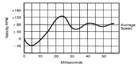 |
Typical starting characteristics for a low speed AC synchronous motor. |
|
| Because of their rapid start characteristics,
careful attention must be given to
inertial loads especially if the load is to be
coupled directly to the motor shaft. As
inertia is increased beyond a certain value,
the available torque decreases. This inertia
is defined by the “knee” in the torque vs.
inertia curve shown below. |
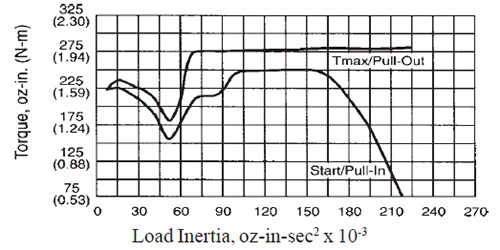 |
Typical torque vs. inertia curves for a low speed synchronous motor. |
|
Also,
operation with less than minimum inertia
can sometimes result in objectionable startup
noise or reduced available torque. The
use of gearing can increase the ability of
these motors to move inertial loads. Speed
change gearing produces reflected load
inertia in proportion to the square of the
gear ratio. For example, a 2 to 1 reduction
from 72 RPM at the motor to 36 RPM at
the load reduces reflected inertia 4 to 1,
and conversely, an increase of speed at the
load to 144 RPM increases reflected
inertia 4 to 1.
Resilient couplings can be used in
applications with high inertial loads to
provide some free shaft rotation so the
motor can start the load. A resilient
coupling should provide approximately five
degrees of rotational freedom before full
load is applied. Standard coupling means
include rubber components, timing belts
and slack chains. On the other hand,
adding a resilient coupling in an application,
with less than the minimum rated system
inertia connected to the motor, may reduce
the available torque.
Low speed synchronous motors can
usually withstand stalls without overheating
since the starting, full load and no-load
currents are essentially the same. However,
the motor will vibrate in prolonged stalled
conditions against a solid stop, which could
cause bearing damage over a period of
time. The stall torque cannot be measured
in the conventional manner, because there
is no average torque delivered when the
rotor is not in synchronization with the apparent
rotation of the stator magnetic field.
Low speed AC synchronous motors
decelerate faster than conventional motors,
usually stopping within a range of 5° to 15°
after turn-off with no external inertia, depending
on the RPM rating of the motor.
Application of DC to one or both motor
windings after removal of AC can produce
deceleration times one-tenth to one-twentieth
of those attainable with a conventional
motor. The motor position remains electrically
locked after stopping. |
| |
| TORQUE MOTORS |
Torque motors are a variation on conventional
induction and DC type motors.
They are designed for duty in slow speed
and tensioning applications. Not only will
they deliver maximum torque under stalled
or “locked rotor” conditions, but torque
machines can maintain a “stall” for prolonged periods, allowing for the controlled
tension essential in such applications
as spooling and tape drives.
Torque motors are especially useful in
three general classes of operation:
- Motor stalled with no rotation
required. Torque motors will operate
like a spring in applications which
require tension or pressure. They can
be easily controlled to change the
amount and direction of force applied.
- Motor shaft to rotate only a few
degrees or a few revolutions to
perform its function. Torque motors
may be used to open or close a switch,
valve or clamping device. In this sense,
they are used as “actuators.”
- The shaft must rotate a major
portion or all of the cycle at a speed
much lower than that of a conventional
motor. Spooling and reel drives
may require torque motor characteristics.
Reel drives may also call for slow
speeds during the “playback” mode,
and higher speeds for short periods in a
rewind or “searching” phase.
AC torque motors are normally of the
permanent split capacitor (PSC) or
polyphase induction type. See Fig.below.
Brush-type motors may also be designed
to operate as torque motors. This would
include shunt and permanent magnet designs which run on DC as well as series
wound torque motors capable of running
on either AC or DC supplies. |
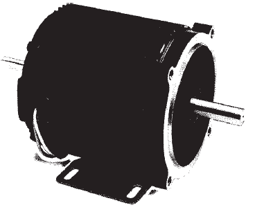 |
Typical AC torque motor. |
|
Torque motor characteristics are usually
obtained by “deviating” from conventional
stator winding, rotor winding
(squirrel cage), rotor lamination and air
gap designs. The Figure below shows the substantially
different speed / torque curves
achieved in one basic motor design
(frame) by changing one or more of the
above-mentioned design parameters.
Curve A is a motor designed for low
slip, high output running performance and
a high breakdown of torque. By changing
one parameter, we can get performance
characteristics indicated by curve B. By
making additional parameter changes, we
can obtain the characteristics shown in
curve C, which is very nearly a straight
line (curve C approaches the “ideal” for
torque motor service).
Because there is a reduction in the
power input, giving the motor prolonged
stall capability, the locked rotor torque in
curve C must be lower than that in the
other two curves. It is common practice
to operate torque motors at different levels
of power input in applications which
have wide variations in torque demand. For example, in tape reel drives, high
speed is needed for fast rewind while
relatively low speeds are required for
recording and playback. |
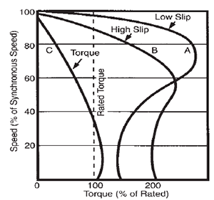 |
Torque motor design vs. high
and low slip motor design |
|
| Reduced output is usually obtained by
reducing the voltage applied to the motor.
This may be accomplished by a variable
ratio transformer, saturable reactor, silicon
controlled rectifier (SCR) supply, or in the
case of small motors, by a series resistor.
The output of a torque motor will be affected
by voltage change in the same way
as conventional motors — by the square of
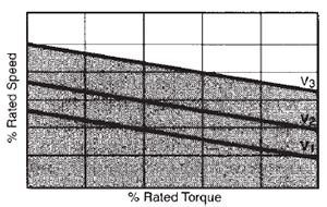
the voltage, as shown in the figure below. While
the curves(shown below)are for a voltage
reduction across the entire motor winding,
it is sometimes advisable to reduce only the
voltage across the main winding of a PSC
motor. This keeps the full line voltage on
the capacitor and capacitor winding combination
so that torque stability at extremely
low operating speeds can be maintained.
When connected in this manner, the torque
can be varied approximately in proportion
to voltage. |
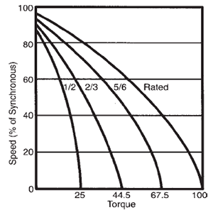 |
Family of speed / torque curves
for various input voltages |
|
Many torque applications require that
the motor be driven against the normal
rotation of its rotating field during a portion
of each cycle. The reverse rotation (resisting)
torque is normally never greater than stalled torque and will decrease slightly as
the reverse speed increases from zero.
A typical tape reel application can be
used to demonstrate this requirement.
When a tape is being wound from one reel
to another, resisting torque is necessary on
one reel motor to provide tape tension.
The voltage is reduced on the motor that
resists being pulled against its normal
rotation to provide the desired tension on
the tape.
There are several specific differences in
rating concepts between conventional induction
motors and their torque motor
counterparts. An understanding of these
differences is essential for proper application.
In contrast to ordinary induction motors,
torque motor input and output are
considered at locked rotor rather than operating
speed. While output is normally
expressed as horsepower or watts, torque
motor output is described as torque
(ounce-inches, ounce-feet, pound-feet or
newton-meters).
The speed rating of a torque motor is
either its “no-load” speed or the theoretical
synchronous speed if the motor is an induction
type.
Duty cycle ratings of torque motors are
also important, and should include two
factors:
- the percentage of the duty cycle during
which the motor may be “stalled” at
rated voltage, and
- the maximum time duration of the stall.
For example, if a motor has a 40% duty
and 30 minute time rating, the motor can
be stalled for 40% of the entire duty cycle,
and the continuous stalled time cannot
exceed 30 minutes out of a 75 minute duty
cycle.
During the remaining 45 minutes, the
motor must be de-energized to permit the
heat generated during the stalled period to
dissipate.
Of course, the duty cycle of this motor
could have many other variations. If the
stalled time was only three minutes, the
total cycle could be as short as 7.5 minutes
(the motor will be de-energized for 4.5
minutes). A motor designed with a torque
sufficiently low to permit continuous stall,
and not exceed the maximum acceptable
temperature, would be rated 100% duty
and a time rating would be unnecessary.
In general, the best torque-to-watt ratio
is obtained in low speed induction motors
(six or more poles). The relationship of
motor poles to torque and speed is shownbelow. Having no commutator or
brushes, induction motors are rugged and
require a minimum of service. The permanent
split capacitor (PSC) motor is by far
the most popular in fractional and subfractional
sizes. It operates on single-phase AC
and has a torque-output-to-watt input ratio
that compares favorably with the
polyphase motor under locked rotor conditions. |
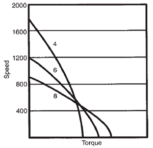 |
Speed vs. torque for various
numbers of stator poles. |
|
Another advantage of the PSC motor as
a torque motor is that it can be designed
with a three-wire reversible winding which
will permit it to be stopped, started and
reversed by a simple single pole / double
throw switch. The shaded pole design may
satisfy some torque motor applications,
but its torque-to-watt ratio is low, and it cannot be reversed.
While the output of a torque motor is
usually taken from the rotor shaft directly,
the motor may have a speed reducing
gearhead through which the torque is increased
by the mechanical advantage of
the ratio minus the losses in gearing. When
a gearmotor is being considered, the gearing
type and ratio are very important and
must be chosen with care. This is especially
true if part of the motor’s function requires
it to be driven by the load, or if the operation
requires the motor and load to be
brought to rest by bumping a rigid stop.
The mechanical parts in a gearhead must
be able to withstand the shocks and stresses
imposed by the application.
Since the torque motor operates either
under a stalled condition or at speeds too
low to provide self-ventilation, it is important
that a motor with a maximum torqueto-
watt ratio be used that will also satisfy
all of the other requirements of the application.
If the operating temperature of the
torque motor chosen for an application
exceeds safe limits, and there is no available
space to accommodate a larger motor,
the problem may be overcome by providing
additional cooling with a low cost,
motor-blower unit. The use of the smaller
torque motor (with the blower addition)
may even result in a cost savings over the
use of a larger motor.
A “fail-safe” brake may also be used to
reduce temperature in torque motor applications.
This would be applicable in cases
where the motor must lift a load to a specific
location and hold it for an extended
period. The brake, connected in parallel
with the motor, would be applied by spring
pressure when power is removed from the
motor. This action will keep the load in
position without any heat being generated. |
Cautions: |
From the above discussion
it is apparent that most torque motor
applications require the use of a sample motor for tests in the machine before determining
final specifications for the optimum
motor. Answers to the nine questions
below should give the motor manufacturer
enough information to supply a sample that
is close to “ideal.” The customer could
then adjust the voltage to the sample to
obtain the desired performance with minimum
input power. Temperature tests
should also be performed in the equipment
under actual or simulated duty conditions.
Consultation with the motor manufacturer
should determine whether modifications or
resizing will be necessary.
Criteria for determining torque motor
applications are:
- What is the available power (voltage,
AC or DC, phase and frequency)?
- What is the torque requirement and
duty cycle?
- What are the minimum and maximum
speeds and how long will the motor
operate at the various speeds?
- Will the motor be driven by the load at
any time in the cycle?
- Is a brake or clutch to be used in the
drive mechanism?
- Will the motor and load be brought to
rest by bumping a rigid stop?
- What mounting space is available?
- Is surrounding air free of dust and
contaminants or should the motor be
enclosed to protect against pollutants?
- What is the ambient temperature?
|
| |
| SWITCHED
RELUCTANCE
MOTORS |
The switched reluctance motor is a type
of synchronous reluctance motor. The stator
and rotor resemble that of a variable
reluctance step motors. See Figure below. The stator of a switched reluctance motor
may have three or four phases as does the
step motor. There are no coils on the rotor
which eliminates the need for slip rings,
commutators and brushes. Both the stator
and the rotor of a switched reluctance motor
have salient poles. |
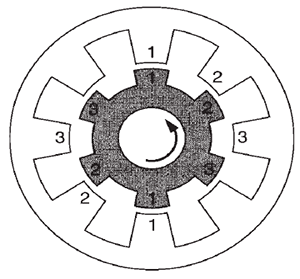 |
Typical switched reluctance
motor design. |
|
The rotor is aligned when the diametrically
opposed stator poles are energized.
Two of the rotor poles will align to the stator
poles. The other rotor poles will be out
of alignment with the remaining stator
poles. When the next stator pole pair is
energized in sequence, they attract the two
rotor poles that are out of alignment. By
sequentially switching the current from one
stator winding to the next, the rotor continually
rotates in a kind of “catch-up” mode
trying to align itself with the appropriate
minimum reluctance position of the energized
stator windings — thus the term,
“switched reluctance.”
The switched reluctance motor provides
inherent characteristics and control functions
that are directly equivalent to DC
servo motors. The torque of the switched
reluctance motor is equal to the square of
the current giving it excellent starting
torque. Motor direction can be reversed
by changing the current switching sequence
in the stator windings. Like their DC counterparts, the brushless design of switched
reluctance motors simplifies maintenance.
Switched reluctance motors cannot be
operated directly from a three-phase AC
supply or a DC source. They require a
controller which adds to their cost. They
are also capable of four quadrant operation,
that is, both speed and torque are
controllable in both negative and positive
directions.
Switched reluctance motors can achieve
very high speeds which may be limited only
by the type of bearings used. This makes
them ideal for high speed applications.
Ironically, their high speed operation causes
considerable noise which is one of their
disadvantages. |
| |
| LINEAR
INDUCTION
MOTORS |
Conventional rotary motors require
some type of rotary-to-linear mechanical
converter (lead screw, rack and pinion,
etc.) if they are used in applications where
the final stage results in linear motion. The
most obvious advantage of linear induction
motors (LIMs) is that they produce linear
motion directly without the need of a transmission
or conversion stage.
The operation of linear induction motors
can be more easily understood if we start
with a conventional rotary squirrel cage
motor, cut the stator and rotor along a radial
plane and roll them out flat. See Figure below. The rotor equivalent of the linear motor
is called the secondary and the stator
equivalent is called the primary. |
 |
Basic linear motor construction |
|
The figure below shows that the primary consists
of a core and windings (multiple phases)
which carry current and produce a
sweeping magnetic field along the length of
the motor. The secondary can be a sheet,
plate or other metallic substance. Linear
motors can have single or dual primaries.
The sweeping action induces currents in the
secondary and thus creates thrust in a given
direction depending on the direction of
current flow. |
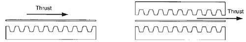 |
Thrust developed by single (left) and dual (right) primary linear motors. |
|
In contrast to a rotary motor, either element
can be the moving element in a linear
motor. LIMs can have a fixed primary and
moving secondary or vice versa. This adds
to their flexibility in a wide range of applications.
The secondary and primary are
separated by a small air gap, typically
0.015 to 0.045 inches. This gap is maintained
by using bearings, wheels or magnetic
levitation.
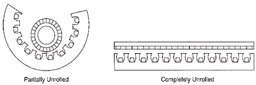
The flat primary can be rolled in the
transverse direction creating a cylinder into
which a tube or rod-type secondary can be
inserted. See Figure below. This is referred to
as a tubular or round rod linear motor. An advantage of this type of linear motor is
that it has no end connections and can be
operated either horizontally or vertically. |
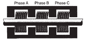 |
Tubular or round rod LIM. |
|
One of the factors that determines LIM
performance is the pitch-to-gap ratio of the
primary coils. It affects the input power
delivered to the secondary and the harmonic
content of the sweeping magnetic
flux. In general, a larger ratio translates into
better performance since it means less harmonics.
Flat LIMs are usually more efficient
than tubular LIMs.
The maximum speed of a LIM is directly
proportional to the operating frequency
and the pitch-to-gap ratio. Speed is varied
by using a variable frequency controller.
LIMs are ideal for applications such as
computer plotters and read head positioning
units, drapery openers, X-ray camera
positioning and a wide variety of conveyor
applications. |
| |
| DC AND AC
SERVO MOTORS |
Servo motors are available in both DC
and AC types. Servo motors are an integral
part of a closed-loop feedback control
system consisting of the motor, an amplifier which drives the motor, an actuator and a feedback device.
A block diagram for a closed-loop system
using a servo motor is shown below. Any change in a system’s load, amplifier
gain or other variable will cause the output
of the system to deviate from the expected
response. In the closed-loop system,
these variations in output are monitored,
fed back and compared to a reference
or desired input. The difference between
the reference and the measured output
signal is a deviation. The deviation is
amplified and used to correct the error.
Therefore, the closed-loop system is selfcorrecting. |
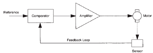 |
Block diagram of a closed-loop control system. |
|
Although servo motors show the basic
performance characteristics of the motor
classes to which they belong (AC
induction, PM DC, etc.), they incorporate
special design features which make them
uniquely suited to applications involving
feedback control. Because servo motors
must be sensitive to a relatively small
control signal, their designs stress reaction
to small voltage variations, especially at
starting.
Both DC and AC servo motors possess
two fundamental characteristics:
- the output torque of the motor is
roughly proportional to the applied
control voltage (which the drive
amplifier develops in response to an
error signal), and
- the instantaneous polarity of the control
voltage determines the torque direction.
AC servo motors are used in the 1/
1500 to 1/8 hp ranges. Beyond this range
AC motors become very inefficient and
difficult to cool. DC servo motors are usually
used in higher hp ranges. |
Direct-Drive Servo Motors: |
In applications where precise positioning
and speed control is required, a directdrive
servo motor is often employed. Direct-
drive servo motors allow the load to
be directly coupled to the motor which
eliminates backlash and wear associated
with other coupling arrangements. Directdrive
servo motors are capable of achieving
fast acceleration and have excellent
response times.
Direct-drive servo motors are usually
brushless and provide all of the advantages
of brushless technology. They may also
have built-in resolvers which provide precise
position monitoring and feedback control.
Position accuracy in the range of 30
arc seconds is typical. |
| |
| SHELL-TYPE
ARMATURE
MOTOR |
While hardly a new idea (patents were
granted for shell-type armature designs
near the turn of the century), shell-type
armature motors have benefited tremendously
from advances in polymer resin
technology. While early armatures were bonded with metal strapping (which contributed
to large eddy current losses), more
recent shell-type designs make use of a
variety of bonding methods which do not
contribute significantly to motor inertia.
These innovations have combined to produce
motors with extremely low inertia and
high acceleration —characteristics which
are useful in many servo applications.
Shell-type armature motors operate in
much the same way as conventional permanent
magnet motors, with an oriented
PM field and commutation by spring-loaded
brushes. The feature that makes shell
armature motors unique is the hollow cylindrical
armature composed of a series of
aluminum or copper coils (“skeins”) bonded
together in polymer resin and fiberglass
to form a rigid, “ironless,” shell. See Figure below. Because the armature has no iron
core, it has very low inertia and rotates in
an air gap with very high flux density. |
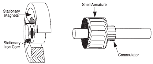 |
Basic construction of a shell-type armature motor. |
|
The unusual design characteristics of the
shell-type armature motor contribute to
low inductance and low electrical time constant
(less than 0.1 millisecond). The absence
of rotating iron in the shell-type armature
motor results in a very high torqueto-
inertia ratio, producing high acceleration
and quick response required in many positioning
servo and incremental motion applications.
The Figure below shows the typical
speed / torque curves for a shell-type armature
motor. |
 |
Typical speed / torque curves
for a shell-type armature motor. |
|
The principal disadvantage to shell-type
armature designs is their thermal time constant
(typically 20-30 seconds for armature,
and 30-60 minutes for housing).
Without proper cooling and/or sophisticated
control circuitry, the armature could be
heated without warning to destructive temperatures
in a matter of seconds during an
overload condition.
Another difficulty is the tendency for
shell-type motors to exhibit audio noise
and output shaft “whip” at high speeds.
Like printed circuit motors, shell-type armature
motors are of somewhat fragile
construction and should be operated in a
more or less controlled environment. Furthermore,
due to the manufacturing techniques
and degree of application engineering
required for this type of motor, they are
relatively expensive and tend to be employed
only where their unique performance
characteristics are required. |
| |